 |
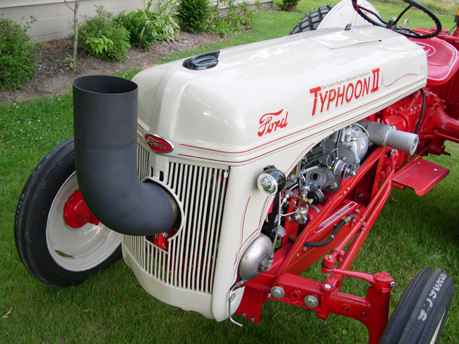
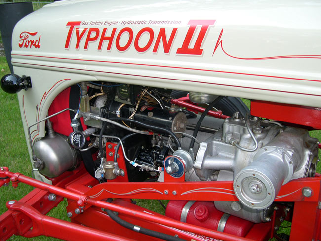
TYPHOON II
This is a gas turbine powered hydrostatic drive tractor.
I felt it more appropriate to rename this tractor “Typhoon II” to honor the original “Typhoon” turbine tractor and it’s builders at Ford Motor Company’s Tractor Division in 1957. |

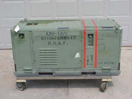
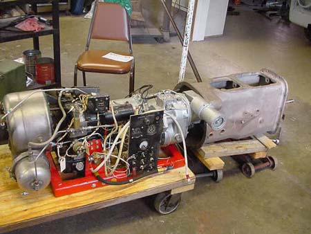
The "APU" as Purchased
|

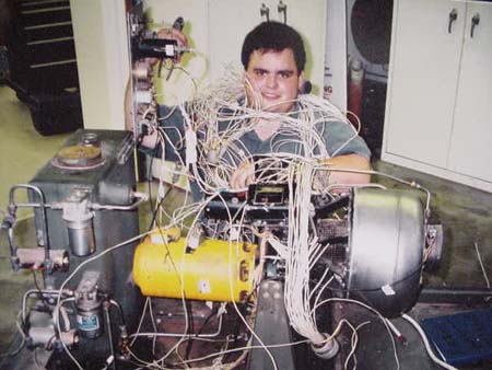
Derek Separating The Wires |

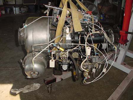
Removing The Engine
|

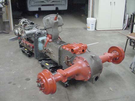
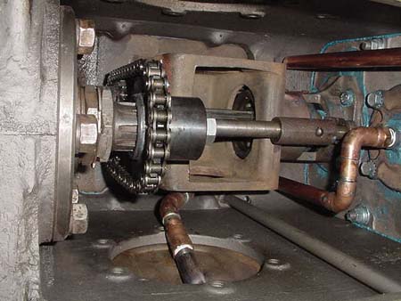
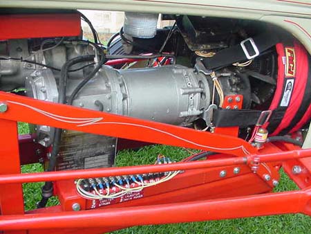
The Hydrostatic Transmission |

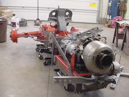
Mating The Parts |

All Connected |

All Connected
|

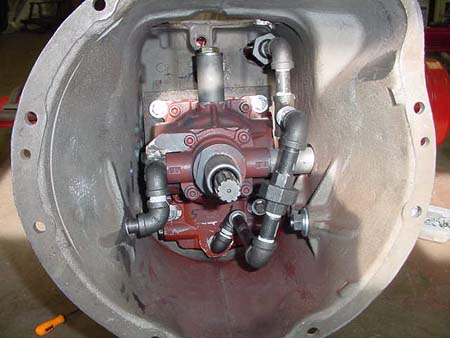
Hydrostatic Transmission Installed |

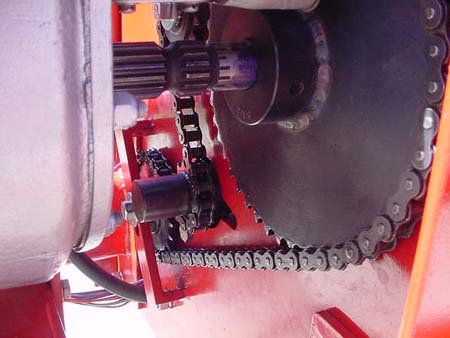
The Sprocket And Chain Drive |

The Differential Connection |

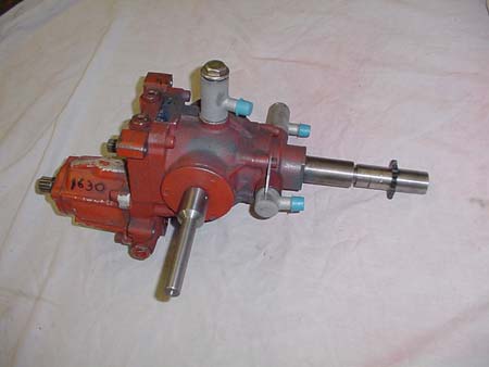
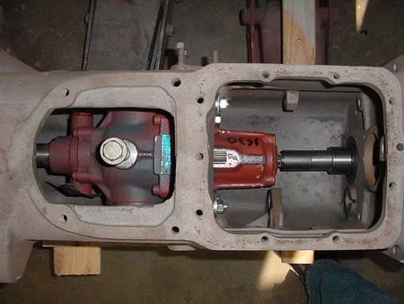
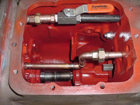
The Hydrostatic Bypass Valve |

Hydrostatic Transmission Installed |

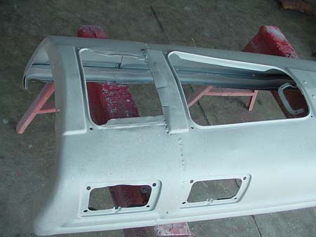
Joining The Two Hoods |

Ready For Sheet Metal Installation |

Detailed By Kurt of "Brushfire" |

The Gearboxes |

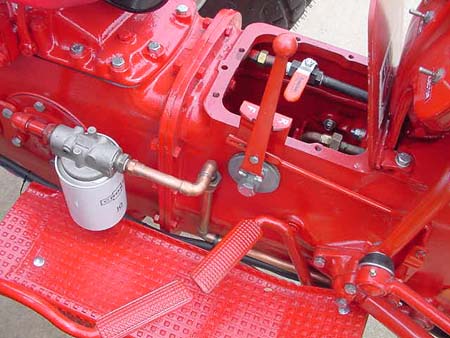
Hydrostatic Filter And Control Lever |
Aircraft Style Dashboard |
|
|
|
|
|
|
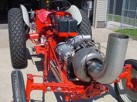
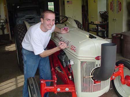
The idea of putting a turbine engine in a Ford 8-N tractor was conceived by me in 1998. I had completed the Ford, Chevrolet and Chrysler V-8 conversions in an 8-N and built "Fourtrans," the 8-N with four transmissions and wanted to do something more challenging. My search to gain knowledge of a turbine engine began on the Internet and led me to Avon Aero in Danville Indiana in August of 2000. Mr. Bruce Linsmeyer, the owner of the company and the countries largest jet engine dealer was consulted to hear of my plans. We first communicated via e-mail and then a personal visit was made to his facility. Upon hearing my plans his recommendation was to use a Garrett Model GTP 30-67 Turboshaft Gas Turbine Engine. This was the engine used in Auxiliary Power Units (APU) that ran generator power plants for the military. The engine was coupled to a 20KW, 400-cycle generator. The engine turns 56000 revolutions per minute and through gear reduction the generator turns 8000 revolutions per minute. After studying the size of the turbine and gearbox in relation to an 8-N, I determined it could become a reality. In August of 2001 I headed to Avon Aero for a second visit and to make the purchase. Upon completion of a training course to run the turbine the complete APU was loaded on my trailer and I headed home filled with enthusiasm. I knew it was going to be a mechanical challenge to adapt this unit to a 50-year-old farm tractor and I began to lie out a plan. I am personally not one to theorize too much on projects such as this one is, but would rather move forward and backup and redo if necessary. The challenge that lay ahead was to get the 8000-RPM down to somewhere around what the tractor originally ran at 1200 to 1500-RPM. After learning the operation of the APU it was determined that I would attempt to leave the unit intact and run the tractor electrically using the generator and now acquire an electric motor and gearbox to match the 400 cycles. It would have to be military as all civilian electric motors run at 60 cycles. I was hoping to use a type of rheostat to control the speed of the motor. My neighbor, Ken Finzel who is an Electrical/Mechanical Engineer lent support as this project was developing. After several inquiries on the Internet I was led to National Aircraft, an aircraft salvage yard in Tucson Arizona. I needed a 400-cycle electric motor coupled with a gear reduction that would make it usable for my conversion. I consulted with Mr. Don Howell of National Aircraft for advise on my project and how he could help me bring it to reality. He said he would study my request and let me know. After a short while he returned my call and mentioned they were disassembling a Boeing B-52 bomber and it had three motors and gearboxes in various locations of the aircraft that may be what I need. After he explained each of them to me I settled on the motors and gearbox that operated the wing flaps of that aircraft. When the heavy boxes arrived I was anxious to see how they could be used. The two motors were made of mostly aluminum and the gearbox was magnesium. I instantly noticed the gearbox had been damaged and a chunk the size of a half dollar was broken out along with the cover over it destroyed. I was able to make a replacement cover but the magnesium gearbox was taken to K & J Fabrication here in Monroe to be repaired. Mr. Ken Clark, owner of K & J Fabrication will be involved in a lot of machining on this project. The motors were taken to Newport Electric for evaluation; Mr. Jim Sonoras would disassemble the motors and report back to me their condition. A week later I got the report that because of their exposure to the elements they would not be repairable. I now had motors and a gearbox that could not be used for their intended purpose. This set plan "B" in motion. The gearbox had a beautiful planetary gear arrangement and resembled a fine oversized Swiss watch. My new plan would be to determine if the gearbox could be driven mechanically rather than its intended electric power. I began disassembling the motors and generator as neither could now be used and determine if I could indeed utilize them somehow in a mechanical drive configuration. It was evident that whatever I decided to do I would have to retain the mounting flange of the generator where it mounts to the engine gearbox and the motor flange where it mounts to its gearbox. I knew I would have to use some type of a hydraulic drive system as it would be very difficult to use a clutch and pressure plate arrangement as there would not be a flywheel to attach them. Also at this time the turbine engine would have to be separated from the generator and literally "miles of wire" removed. Removing the wire was easy but now we would have to figure out how to rewire the turbine eliminating all the unnecessary features and all the redundancy used by the military. I began my search for help on the Internet with a person who had the same turbine engine as I had. My first contact was with a gentleman who resided in the Netherlands. He was very helpful along with Jerry Green owner of the same type turbine as mine who resides in Indiana. I now had all the information I needed to get the engine running but with my lack of knowledge of electrical circuitry I now needed an electrical genius to decipher the information I had and apply it. Enter my nephew, Derek Cole a computer guru who became obsessed with getting the turbine operational. It took a couple of sessions and we had it running again. I went to my local New Holland dealer and consulted with the service manager, Ron Gerber to learn about a hydrostatic drive unit. After a couple of visits with Ron a search was on for a hydrostatic drive unit. Our search ended with a unit that was used on a model 1630 New Holland tractor and it was purchased. With the criteria now determined, I loaded the housings of the generator and the frame of one of the motors along with the stripped shafts of the motor armature and generator and was off to see Ken at K & J Fabrication. Giving Ken the dimensions I needed to maintain he then cut both housings and shafts. Using the dimensions furnished to him he welded the aluminum generator and motor housings together and welded the two shafts from the motor and generator to match the length of the housing. We now had a mechanical hookup to the gearbox. The Boeing B-52 gearbox could not be used in its intended operating position. I had to rotate it 90 degrees for clearance and had to be sure of a positive lubrication for the high speed gears that were formerly oiled under oil pressure. This was accomplished my determining a new oil level in the gear case to assure the adequate lubrication of all the gears. With all of this installed I was now able to determine the revolutions of the output shafts; there are two output shafts that I could use on the B-52 gearbox. Spooling up the turbine let up put a handheld tachometer on each shaft. The final output of the shaft to be used was 330 RPM or a 24:1 reduction. This was much too slow for the intended use of the tractor and I would now have to speed it up to at least 1200 RPM. I determined this would have to be done using either gears or a chain and sprocket system. In working out a system another situation developed, the gearbox was rotating in the opposite direction for the hydrostatic drive to function. After consulting with K & J Fabrication it was determined we would use a chain and sprocket system utilizing an idler gear positioned opposite the drive gear. We would then run the hydrostatic transmission off the backside of the chain thus reversing the drive to the transmission. It was decided to have a bypass valve installed on the hydrostatic unit that would route the hydraulic oil from the hydrostatic pump into the sump until full RPM's were reached on the engine. When full RPM's are reached on the engine the valve is closed and the oil from the pump is now routed through the hydraulic motor in the hydrostatic drive unit. Now that we had the mechanics of the unit determined and built the next step would be to design and build a frame for the tractor on which the front axle would mount. It was a sure thing that I would not be able to mount the axle in the original height position because of the low position of the combustion chamber on the turbine engine. I mounted the axle as high as I could and then cut relief's in the axle to clear the combustion chamber. The other problem with mounting the front axle was the angle of which it was originally formed. It was heated and pressed and reformed to achieve the desired angle I needed for clearance. Now there was the problem of getting the axle position lowered to have the tractor sit at the proper angle. This was accomplished by sectioning the spindle housings. A two-inch section was removed from the housing from below the front axle level, and replaced on top of the front axle level. The radius rods and tie rods were extended and re-formed to conform to the increased length of the tractor. A new battery box was designed to fit into the original 8-N location. The new battery box is twice the size, as the turbine engine requires a twenty-four volt system and subsequently two 12-volt deep cycle marine batteries. The fuel tank used is the same tank as originally used with the turbine engine in its original configuration. It is an aluminum tank with an electric fuel pump mounted on it. The fuel tank is mounted on the rear on the tractor. Then came the wiring. The turbine engine and equipment operates on 24 volts. For this purpose I used two heavy-duty deep cycle marine batteries wired in a series configuration. I am also running other accessories on 12 volts that I wired into only one of the batteries. When I originally started this project I knew of the knowledge I would have to gain to operate a turbine engine. What I was not prepared for was any repairs that would have to be made. The engine ran fine in the generator setup when purchased. On initial startup in the tractor chassis the engine would only spool up to 70% of its efficiency. I made contact with Bruce Linsmeyer of Avon Aero who gave me valuable advise as to what could cause the problem I was having. After exhausting the probable causes with no success including disconnecting the gearbox, it was time to start replacing parts. Bruce sent me a pneumatic thermostat, a fuel atomizer and a fuel control unit, which is the brain of a turbine engine. I started with the simple part changes, which was the pneumatic thermostat and the fuel atomizer with no success. Next was the bigger task of replacing the fuel control unit. With this control replaced the engine problem was overcome and it was now performing at 100% efficiency. Now the real test of the engine was coming. The reconnection of the gearbox and connecting the chain to the hydrostatic drive unit to see if the engine would move all of these components during spool up. This particular turbine engine operates at full RPM's and does not have power as it is rising to 100%. I jacked up the rear tires of the tractor, and got ready to start the engine in anticipation and hopes that it would reach full power while driving the hydrostatic transmission. I opened the fuel valve, turned on the power switch and electric fuel pump, lifted the starter switch and ran the engine up to 20% efficiency or 10,000 RPM and hit the igniter. Combustion occurred and the engine RPM kept increasing until it reached its peak of 100% efficiency or 56,000 RPM. At that point I had a great level of confidence as the hydrostatic transmission pump was now operating. Next I closed the relief valve between the hydrostatic pump and motor and fluid was now flowing through the hydrostatic motor. Next I shifted the selector lever into forward and the wheels began turning, what a thrill. I then put it back in neutral and then reverse and the wheels again went into action. The adrenaline was flowing in my body, as I knew I was ready to make my first trip on the tractor. I asked my neighbor Tom Steinke who was with me on this maiden voyage to lower the jack and get the wheels back on the ground. I moved approximately 100 feet forward and back. I now felt my project was a success and I was now ready to finish the sheet metal. The hood was extended 9 1/2". Cutting two hoods and then joining them together to the new extended length accomplished this task. Then the grill had to be reworked to allow an exit for the exhaust. Lots of metal work involved in this project. Then the completed project was painted using New Holland paint and synthetic enamel hardener. A metal shield was formed and a high tensile blanket was wrapped around the engine combustion chamber for safety. With all these tasks completed it was now time for a professional sign painter to complete the lettering and pin striping. With this project completed I felt a great sense of accomplishment in the fact that I have a "One of a kind" piece of machinery. The whole project was conceived to be a self-challenge and my goal was accomplished. Upon completion of this project I was able to learn through the Internet and magazine articles that both Ford and the International Harvester Companies had built prototype turbine powered tractors. Ford built the Typhoon in 1957 and International built the HT-340 in 1961. The disposition of the Ford is unknown and the International is in the Smithsonian Institution. It was remarkable to me when I read of the International HT-340 and how parallel the design was to the "Typhoon II " tractor that I created.
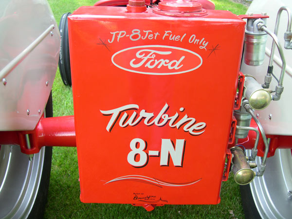
| Designed and built by Marvin Baumann over a two year period from August 2001 to May 2003 when it was completed. |
|
|
| |
|
|